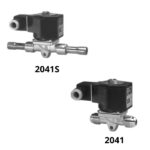

Principal Characteristics
|
andecologicalrefrigerants(HFC)/zoom/21462480903_2.jpg) |
Technical specifications
| Size | Connection | Catalog Nr. | Kv Coefficient | Weight in Kg. (*) | Repair Kit Code | |
| 1/4″ | Flare | 2041BT2 | 0,16 | 0,49 | K41T1 | |
| Soldar odf | 2041BT2S2 | 0,48 | ||||
| 3/8″ | Flare | 2041BT3 | 1,20 | 0,54 | K041T1 | |
| Soldar odf | 2041BT3S3 | 0,59 | ||||
| 1/2″ | Flare | 2041BT4 | 1,40 | 0,55 | ||
| Soldar odf | 2041BT4S4 | 0,59 | ||||
| 5/8″ | Soldar odf | 2041BT4S5 | 0,60 | |||
| Flare | 2041BT5 | 2,50 | 0,92 | K41T3 | ||
| Soldar odf | 2041BT5S5 | 0,95 | ||||
| 2/4″ | Soldar odf | 2041BT5S6 | 2,70 | 0,96 | ||
| 7/8″ | Soldar odf | 2041BT5S7 | 0,97 |
- (*) The weight includes valve and coil.
- General dimensions
andecologicalrefrigerants(HFC)/zoom/32015676209_3.jpg)
| Connection | Catalog | Part Nr | DIMENSIONS (mm) | |||||||
| fA | B | C | D | E | F | G | fH | |||
| 1/4″ FLARE | 2041BT2 | 041BT2 | – | 30 | 53 | 7,7 | 64,3 | 59 | 87,3 | – |
| 1/4″ ODF | 2041BT2S2 | 041BT2S2 | 6,40 | 115 | 115,3 | |||||
| 3/8″ FLARE | 2041BT3 | 041BT3 | – | 40,5 | 67 | 17,5 | 65 | 77 | 96,3 | 5 |
| 3/8″ ODF | 2041BT3S3 | 041BT3S3 | 9,66 | 150 | 132,8 | |||||
| 1/2″ FLARE | 2041BT4 | 041BT4 | – | 77 | 96,3 | |||||
| 1/2″ODF | 2041BT4S4 | 041BT4S4 | 12,76 | 150 | 132,8 | |||||
| 5/8″ ODF | 2041BT4S5 | 041BT4S5 | 15,9 | |||||||
| 5/8″ FLARE | 2041BT5 | 041BT5 | – | 54,5 | 98 | 19 | 75,5 | 102 | 108,8 | 7 |
| 5/8″ ODF | 2041BT5S5 | 041BT5S5 | 15,9 | 170 | 142,8 | |||||
| 3/4″ ODF | 2041BT5S6 | 041BT5S6 | 19,1 | |||||||
| 7/8″ ODF | 2041BT5S7 | 041BT5S7 | 22,3 | |||||||
andecologicalrefrigerants(HFC)/zoom/41672390740_4.jpg)
- NOTES: (**) Upon request Pg11 or 1/2″ NPT conduit.
- Optional luminous indicator.
-
Recommendations for the installation of solenoid valves - Place a strainer immediatly upstream of the valve.
- Most favourable position: Upon a horizontal pipe line with the coil in the upward position.
Instructions for brazing
- Desassemble the valve leaving only the body.
- Place a wet rag on the body as shown above to avoid excessive heat build-up.
- In the case of extended copper tubes it is not necessary to disassemble the valve.
- When reassembling the valve proceed with caution in the handling of the different pieces, particularly with the Teflon diaphragm.
andecologicalrefrigerants(HFC)/zoom/5947597200_5.jpg)
-
Typical circuit for the Dt regulation for chambers with relative humidity control. - 1. Strainer
- 2. Solenoid valve
- 3. Thermostat
- 4. Check valve
- 5. Thermostatic expansion valve
- 6. Evaporator
- 7. Pressure-switch
andecologicalrefrigerants(HFC)/zoom/61611159426_6.jpg)
This system replaces the suction pressure regulator valve.

